
Note: since posting this, the completed air test documents show a result of 0.2 air changes per hour.
It's been a while since I've posted during the always-longer-than-the-client-expects period where all the finishing work is completed.
We have started the process to get Certification as a Passivhaus, using the UK's top certifier and general guru on all things building physics related, Warm Low Energy Practice. Yesterday, Paul Jennings ("doorfanman"), our airtightness consultant completed the official airtightness test and we got:
0.19 air changes per hour!
This is a really big improvement on April's test. Partly because I calculated the internal volume more accurately, using Bluebeam, which has a great tool for measuring dimensions, areas etc of PDF plans. Our internal ventilation volume is 442.38m³ and the April test had been based on a rougher calculation of 400m³. Mostly though, the information from the April test helped us to to improve the weak areas.
It will be interesting to see how durable our result is. We believe we have created an airtightness layer which lasts.
I had already put up a DIY shelf in one of the rooms before yesterday's test was conducted, which required drilling a few holes into the plaster than forms the airtightness layer in the external walls of the refurbished part of the house. I put some sealant into the holes before inserting raw-plugs. Obviously, I will be aware of the need not to drill holes in the original external walls without thinking about airtightness. In the new build section, where the airtightness layer is beneath a 50mm service void, I will not have to worry nearly as much about affecting airtightness. For this reason, in any new build, I would always want to design in a service void. I think that, in the real world, it stands a much better chance of remaining intact over the design life of the building.
Next week, our MVHR (heat recovery ventilation unit) will be commissioned. This will involve, amongst other things, calibrating the airflow to each supplied room (and from each extracted room) to:
a) ensure that there is an appropriate air change rate for the use of the room
b) ensure that sufficient heat is delivered to the rooms (the tiny trickle of heat needed in a Passivhaus is delivered via the supplied air in the ventilation system)
c) ensure that the total rate of air supplied equals the total rate of air extracted. This is important because if the two are not in balance, the MVHR wastes electrical energy and because it results in the house being slightly over or under pressure, it will increase the flow of air through the fabric of the building.
Showing posts with label airtightness. Show all posts
Showing posts with label airtightness. Show all posts
Friday, 22 July 2011

Wednesday, 6 April 2011
0.4 air changes per hour!!
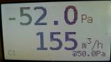

We should be able to improve on that figure in the final test needed for Certification, as we were able to identify the relative weak points.
We spent a little time today working out how much extra time we spent into doing tasks that were necessary to achieve it. Our conclusion was that it was not a significant extra task. However, everyone in our team are really committed to paying attention to protecting the airtightness layer. We have not had to have a formal "Airtightness Champion" trying to watch everyone constantly, in case it was damaged.
Watch a clip of the airtightness test on YouTube: http://www.youtube.com/watch?v=nMTLfj4iXec
Monday, 4 April 2011
First airtightness test
Tomorrow (5th April) is a big day for the project. Paul Jennings from ALDAS, will be conducting our first airtightness test. We have been preparing for the day by going through the whole building to ensure there are no forgotten gaps or holes.
All the windows are now in and although there are still snags and issues to be resolved, they all close well enough for the airtightness test. In the refurbished part of the house, the windows are mounted on the ouside of the original walls with the external insulation wrapping around the window frames to minimise the thermal bridging around the window edge. This also minimises the area of window frame, which helps aesthetically and improves the energy performance of the window installation because window frames are generally the poorest performing part of the window. The photo below shows a section of a window with the first of four layers of insulation attached around it.

The next photo shows another section of window with all 180mm of phenolic foam in place. The work to cut and attach the insulation was time-consuming and really unpleasant for the team - the stuff makes you really itchy. The job was made more difficult because Kingspan would not supply their product in broad sheets of 100mm and 80mm depths. Instead we had thinner (40mm and 50mm) and smaller area sheets. This meant much more glueing and cutting. We have also had to use more of the fixings than would have been needed with the broader sheets. Thank you Kingspan.

In the photo below, the airtightness tape is being applied to along the base of the window, forming a seal between the window frame and the previously parged internal window reveal. We probably have not approached this very well, as the process took longer than expected and was very fiddly. Because the parge layer was rougher than is ideal, we felt we needed to use an adhesive primer in addition to the Tescon Profil tape. It was hard to control what then becomes a very sticky combination of materials! We will need to check back with suppliers, Ecological Building Systems, to try to do it better next time.

We have two large service penetrations into the roof: for the soil vent pipe (SVP) and for the flue. We are using a small gas boiler, which modulates down to about 4kW, to provide our winter hot water - solar thermal will deliver the rest - and any residual heating we may need in the coldest weather. As well as an airtightness issue, SVPs and flues create a potential thermal bridges. The flue has a pair of concentric pipes, the inner one to vent exhaust gases and an outer ring to take in air to the boiler for the combustion process. The flue runs through a grommit/Intello, past 350mm of Warmcel, 22mm of Steico wood fibre board and through the Solitex roof underlay. It could therefore, unless insulated around the pipe within the house, be a significant thermal bridge. We are planning to enclose it, and the SVP, which presents similar issues, with sheep's wool insulation within the boxing. The lack of a need for a flue in an electricity based heating system, i.e. a heat pump, makes gas a less attractive option in a Passivhaus. However, I must admit that the extra cost of a heat pump based solution put me off a bit when we were at the design stage. The Passivhaus Institute are keen to encourage manufacturers to develop and sell "compact units". These have about the same footprint as a fridge freezer - so are super space efficient - and combine the MVHR, hot water (DHW) and space heat product functions in a single unit. One, the Compact P made by Danish manufacturer Nilan, has been Certified by the Passivhaus Institute, and is being promoted in the UK. It looks quite promising, however, most combined devices don't deliver the same performance as the "separates" units would. Our MVHR unit is almost twice as electrically efficient as the Nilan Compact P. And I think compact units need to be completely modular in design, so that parts that fail can be replaced independently of the rest of the machine. The other argument in favour of using heat pumps for DHW and space heating is that they will be better in climate/CO2 terms than gas, as the renewables portion of the electricity grid mix grows. I think that in another five or ten years, the balance - and the economics - may well have shifted in favour of heat pumps and I hope compact units.

We also have two large penetrations for the heat recovery ventilation (MVHR) unit's intake and exhaust ducts. The ducts themselves are 160mm but are wrapped in 125mm of insulation, making the penetrations 410mm each! This photo is from the inside, where the ducts meet the airtightness barrier, which in this part of the building is the internal plasterwork (parge coat). The walls are still to have their finishing layers of plaster, which will encase the grommit, intello and tescon tape. The continuation of the ducts will also have 125mm of insulation right up to the insulated surround of the MVHR unit.

All the windows are now in and although there are still snags and issues to be resolved, they all close well enough for the airtightness test. In the refurbished part of the house, the windows are mounted on the ouside of the original walls with the external insulation wrapping around the window frames to minimise the thermal bridging around the window edge. This also minimises the area of window frame, which helps aesthetically and improves the energy performance of the window installation because window frames are generally the poorest performing part of the window. The photo below shows a section of a window with the first of four layers of insulation attached around it.

The next photo shows another section of window with all 180mm of phenolic foam in place. The work to cut and attach the insulation was time-consuming and really unpleasant for the team - the stuff makes you really itchy. The job was made more difficult because Kingspan would not supply their product in broad sheets of 100mm and 80mm depths. Instead we had thinner (40mm and 50mm) and smaller area sheets. This meant much more glueing and cutting. We have also had to use more of the fixings than would have been needed with the broader sheets. Thank you Kingspan.

In the photo below, the airtightness tape is being applied to along the base of the window, forming a seal between the window frame and the previously parged internal window reveal. We probably have not approached this very well, as the process took longer than expected and was very fiddly. Because the parge layer was rougher than is ideal, we felt we needed to use an adhesive primer in addition to the Tescon Profil tape. It was hard to control what then becomes a very sticky combination of materials! We will need to check back with suppliers, Ecological Building Systems, to try to do it better next time.

We have two large service penetrations into the roof: for the soil vent pipe (SVP) and for the flue. We are using a small gas boiler, which modulates down to about 4kW, to provide our winter hot water - solar thermal will deliver the rest - and any residual heating we may need in the coldest weather. As well as an airtightness issue, SVPs and flues create a potential thermal bridges. The flue has a pair of concentric pipes, the inner one to vent exhaust gases and an outer ring to take in air to the boiler for the combustion process. The flue runs through a grommit/Intello, past 350mm of Warmcel, 22mm of Steico wood fibre board and through the Solitex roof underlay. It could therefore, unless insulated around the pipe within the house, be a significant thermal bridge. We are planning to enclose it, and the SVP, which presents similar issues, with sheep's wool insulation within the boxing. The lack of a need for a flue in an electricity based heating system, i.e. a heat pump, makes gas a less attractive option in a Passivhaus. However, I must admit that the extra cost of a heat pump based solution put me off a bit when we were at the design stage. The Passivhaus Institute are keen to encourage manufacturers to develop and sell "compact units". These have about the same footprint as a fridge freezer - so are super space efficient - and combine the MVHR, hot water (DHW) and space heat product functions in a single unit. One, the Compact P made by Danish manufacturer Nilan, has been Certified by the Passivhaus Institute, and is being promoted in the UK. It looks quite promising, however, most combined devices don't deliver the same performance as the "separates" units would. Our MVHR unit is almost twice as electrically efficient as the Nilan Compact P. And I think compact units need to be completely modular in design, so that parts that fail can be replaced independently of the rest of the machine. The other argument in favour of using heat pumps for DHW and space heating is that they will be better in climate/CO2 terms than gas, as the renewables portion of the electricity grid mix grows. I think that in another five or ten years, the balance - and the economics - may well have shifted in favour of heat pumps and I hope compact units.

We also have two large penetrations for the heat recovery ventilation (MVHR) unit's intake and exhaust ducts. The ducts themselves are 160mm but are wrapped in 125mm of insulation, making the penetrations 410mm each! This photo is from the inside, where the ducts meet the airtightness barrier, which in this part of the building is the internal plasterwork (parge coat). The walls are still to have their finishing layers of plaster, which will encase the grommit, intello and tescon tape. The continuation of the ducts will also have 125mm of insulation right up to the insulated surround of the MVHR unit.

Sunday, 20 February 2011
Forming an airtight wall-ceiling junction
We have started to create the airtightness layer at various points in the building. In this post, I will describe the sequencing for one of our ceiling-wall junctions. The airtightness layer in this part of the build is formed by plaster on the wall and by Intello vapour barrier on the underside of the roof I-beams.
Stage 1) The Intello was stapled to the underside of the I-beams. Tescon tape was applied to join up each row of Intello. We also taped over the staples, in case the Intello is stretched and a small gap appears around the staples, although apparently this is not strictly necessary to achieve the Passivhaus 0.6 air changes per hour (ach) target.
Stage 2) In order to join the plaster to the Intello, we used Contega PV tape - half adhesive backed, half mesh. We had to use Tescon tape to stick the Contega to the Intello, as the Contega adhesive would not stick properly to the Intello. I had a very helpful conversation with Niall Crosson from Ecological Building Systems where he told me that if the Intello is exposed to humidity, it can affect its ability to stick to the Contega. I guess this must be because of the property of the Intello to vary its vapour permeability according to the ambient humidity.
Stage 3) After the first photo below was taken, an initial parge layer was applied under the Contega. We took care to put a kink along the length of the Tescon tape by pushing it up slightly, to allow for any possible future movement between wall and ceiling.


Stage 1) The Intello was stapled to the underside of the I-beams. Tescon tape was applied to join up each row of Intello. We also taped over the staples, in case the Intello is stretched and a small gap appears around the staples, although apparently this is not strictly necessary to achieve the Passivhaus 0.6 air changes per hour (ach) target.
Stage 2) In order to join the plaster to the Intello, we used Contega PV tape - half adhesive backed, half mesh. We had to use Tescon tape to stick the Contega to the Intello, as the Contega adhesive would not stick properly to the Intello. I had a very helpful conversation with Niall Crosson from Ecological Building Systems where he told me that if the Intello is exposed to humidity, it can affect its ability to stick to the Contega. I guess this must be because of the property of the Intello to vary its vapour permeability according to the ambient humidity.
Stage 3) After the first photo below was taken, an initial parge layer was applied under the Contega. We took care to put a kink along the length of the Tescon tape by pushing it up slightly, to allow for any possible future movement between wall and ceiling.

Stage 4) Once it had dried, a second layer was applied to encase the mesh and the Contega tape above it. Then battens were screwed through the Intello to the I-beams. The Intello grips the screws and forms an airtight seal around them, which is only compromised if the screw is removed: it is vital therefore not to remove a screw if it has been incorrectly positioned - better to leave it in place. The space above the Intello (i.e. between the I-beams) is to be filled with Warmcel cellulose, so the battens will help the Intello support the weight of the Warmcel and will provide a 25mm service void to the ceiling plasterboard. 25mm is normally too narrow but I didn't want headroom to be reduced any more than is necessary in this attic space.

The remainder of the wall will be plastered later, along with the ceiling.
Thursday, 27 January 2011
Airtightness around existing floor joists (and along the top of internal walls)
The last few weeks has seen tremendous progress on the build and one issue that I wanted to focus on in this post is how we managed airtightness around the ends of the existing floor joists.
The picture below shows how the floor joists looked before. Normally, the block work would only be plastered above and below the joists, where the finished wall would be visible. In a Passivhaus refurbishment, the plastering needs to run continuously around the joists.

We had originally intended to keep the plasterwork below, if it was sound enough, but mostly it just fell off with minimal if any encouragement. As discussed in a previous post, water penetration in the cavity, due to poor detailing at the original roof-wall junction, together with some poor choices with the original render and paintwork seemed to have been the cause.
The issue of how to make airtight joist ends has been covered in this AECB YouTube video. One of the key points they mention is that the approach needs to take account of whether the wall is going to be insulated internally or externally. If a wall is to be internally insulated, there will be a significant temperature drop at the end of the joist, which brings a risk of condensation because the joist end sits within the cold wall. In the film, to avoid this, they have mounted the joists on joist hangers on an internally insulated wall. Steps then need to be taken to achieve airtightness around the joist hangers.
In our project, the existing house is being insulated on the outside, so the inner leaf of the existing cavity wall will be the same temperature as the inside - i.e. no condensation risk. This has been our approach to achieving airtightness around the joist ends:
Stage One
Carlite Bonding parging around the joists onto the original concrete block wall or sometimes new built sections of Thermalite block wall:

The same principle has been applied to a steel girder fabricated with an additional L-shaped piece, welded with the bottom of the L welded to the web of the girder. This means that the profile of the end of the girder is a solid rectangle, like a joist end, rather than an "I" profile, simplifying making it airtight.

Stage Three
Taping around the joist and girder ends using Pro Clima's Tescon Profil tape.


Stage Four
Dotting the corners with Pro Clima's Orcon F adhesive. This is a "belt-and-braces" step. We were not absolutely sure that our tape corner junctions would stay completely airtight. We applied dots of Orcon F to be sure!

Stage Five
Apply Unibond to the Tescon tape to provide a key for the second parge layer (next stage).
Stage Six
Apply a second parge layer to seal in the Tescon tape. In the picture below, the joist on the left was originally a double joist. We cut short the thinner of the two rather than try to treat the double joist along its length. Obviously, if the double joint were needed for structural reasons, we would not have been able to cut one joist back.
 Dealing with the edge joists
The joists run north-south in our build. There was no edge joist on the east side due to the run of the original roof rafters, however the edge joist on the west wall was mounted close up against the wall and there wasn't enough space around the joist ends to parge and tape around them. One option was to wrap the entire length of the joist in Intello Plus membrane, then tape it down above and below the joist. We decided it was more practical to cut out the existing joist, reduce its length a few cm and re-attach it with coach bolts along its length of the west wall. We used resin anchor gel to secure the bolts in the wall but also applied a generous ring of Orcon F around each a penetration to provide a flexible airtight seal (picture below).

The picture below shows how the floor joists looked before. Normally, the block work would only be plastered above and below the joists, where the finished wall would be visible. In a Passivhaus refurbishment, the plastering needs to run continuously around the joists.

We had originally intended to keep the plasterwork below, if it was sound enough, but mostly it just fell off with minimal if any encouragement. As discussed in a previous post, water penetration in the cavity, due to poor detailing at the original roof-wall junction, together with some poor choices with the original render and paintwork seemed to have been the cause.
The issue of how to make airtight joist ends has been covered in this AECB YouTube video. One of the key points they mention is that the approach needs to take account of whether the wall is going to be insulated internally or externally. If a wall is to be internally insulated, there will be a significant temperature drop at the end of the joist, which brings a risk of condensation because the joist end sits within the cold wall. In the film, to avoid this, they have mounted the joists on joist hangers on an internally insulated wall. Steps then need to be taken to achieve airtightness around the joist hangers.
In our project, the existing house is being insulated on the outside, so the inner leaf of the existing cavity wall will be the same temperature as the inside - i.e. no condensation risk. This has been our approach to achieving airtightness around the joist ends:
Stage One
Carlite Bonding parging around the joists onto the original concrete block wall or sometimes new built sections of Thermalite block wall:

The same principle has been applied to a steel girder fabricated with an additional L-shaped piece, welded with the bottom of the L welded to the web of the girder. This means that the profile of the end of the girder is a solid rectangle, like a joist end, rather than an "I" profile, simplifying making it airtight.

Stage Two
Priming around the joist ends with Pro Clima's Tescon Primer adhesive. This helps to make sure the Tescon tape sticks to the plaster.
Stage Three
Taping around the joist and girder ends using Pro Clima's Tescon Profil tape.


Dotting the corners with Pro Clima's Orcon F adhesive. This is a "belt-and-braces" step. We were not absolutely sure that our tape corner junctions would stay completely airtight. We applied dots of Orcon F to be sure!

Apply Unibond to the Tescon tape to provide a key for the second parge layer (next stage).
Apply a second parge layer to seal in the Tescon tape. In the picture below, the joist on the left was originally a double joist. We cut short the thinner of the two rather than try to treat the double joist along its length. Obviously, if the double joint were needed for structural reasons, we would not have been able to cut one joist back.

The joists run north-south in our build. There was no edge joist on the east side due to the run of the original roof rafters, however the edge joist on the west wall was mounted close up against the wall and there wasn't enough space around the joist ends to parge and tape around them. One option was to wrap the entire length of the joist in Intello Plus membrane, then tape it down above and below the joist. We decided it was more practical to cut out the existing joist, reduce its length a few cm and re-attach it with coach bolts along its length of the west wall. We used resin anchor gel to secure the bolts in the wall but also applied a generous ring of Orcon F around each a penetration to provide a flexible airtight seal (picture below).

Sunday, 14 March 2010
A lot has happened since the last post. I have been working on the Passive House Planning Package (PHPP), the very sophisticated Excel based spreadsheet used to model how your proposed building will perform. I had spent a lot of time getting to grips with the basics of entering our proposed building's parameters - areas, materials, glazing, window frames; together with the climate and any shading - which is a bit tedious but which has to be done accurately if you want the PHPP to predict how the real life building will perform. It was only when I started getting initial estimates of how the building would consume, especially whether we were going to make it down to the magic 15kWh/m2/annum, that the power and usefulness of the PHPP really became apparent.
Since then, I have been refining the information going into the PHPP and it has allowed us to pinpoint the problem areas and tweak the design further to optimise performance. The floor is still our biggest obstacle. It definitely does not not make sense to remove the slab, as this would also mean removing all the internal supporting walls, all of which we would otherwise want to keep. My earlier modelling of the floor-wall junction may have been too optimistic, as I had only assumed a temperature of zero outside, when -10C would be a more realistic worst case. Also, the outside walls will likely perform better, as they will have insulation outside, right down to the footings. The inside walls won't have this insulation and are therefore probably a bigger thermal bridge.
We have added south facing glazing in the roof, following a visit to Ecobuild earlier in the month. Velux now do a triple glazed window with an overall U-value of 0.82. The window has an integrated external blind (essential in a south facing roof window) with remote controlled operation - even though I am not keen on excessive complexity and gadgetry built into the fabric of the house, when the window is 4m or 5m up, I'm willing to make an exception. I had wanted to avoid using roof windows, as I think it is very hard to avoid thermal bridging around the frame. How a window is installed makes a huge difference to its performance. Even with good double glazing, the way it is installed can boost or degrade its rated performance a lot. In a Passivhaus, as well as avoiding thermal bridging, the window has to be fitted to create an air-tight seal around the frame and set in the wall so that the wall reveals and overhang do not create additional shadowing on the window. In a standard block or brick built house, this means wrapping the external insulation around the window frame on the outside so that the window frames will look quite slim from the outside. Also, the rough opening, into which the window is to be installed, needs to be plastered accurately and smoothly, and let to dry out fully, before the window is installed. This allows the specialist tapes, used to make the building airtight, to be fixed between the window frame and the plasterwork to form a good air-tight seal. This changed sequencing of work is quite different to conventional builds but is essential in a Passivhaus. These tapes should be used around the frame, even when air-tight bands are placed between the frame and rough opening. Such bands are designed to expand once in place, so making a good seal but the tape provides a second layer of airtightness and it is easier to patch it if the building fails it's airtightness testing during the build (more of this later).
Visiting Ecobuild, it was possible to compare triple glazed windows. Many only have a single rubber gasket to maintain the airtight seal between the opening section and the frame. Although it may perform adequately when the Passivhaus is first commissioned, it is likely to fail over time. Better designs have double or treble gaskets and use engineered wood, which does not warp nearly as easily as its non-engineered counterpart.
On airtightness testing, we will need to test at two points during the build: after the windows go in but before the 'first fix' and again after first fix. This is essential because there is not much point in identifying any failures in the building's airtightness after it is all finished. It is much easier and cheaper to resolve problems before all the finished surfaces and fittings are put in.
On a wider note, new passive houses are between to get formal certification from the Passivhaus Institute. One of the latest was a house in Kent featured on Grand Designs. Congratulations to them! We will kick off the process for getting certification after we have got through planning.
We want to get our planning application off this week. In a conventional build, we could have sent our application off some time ago but in a Passivhaus this is much more risky as we had to do a lot more detailed design work, aided by the PHPP, to get the building working right first, before we could apply for planning permission. Otherwise we might have found ourselves unable to change something that is crucial to the building's energy performance. This might be a real barrier for some people, as it means spending more on architect's fees while the project is still not certain to go ahead.
Subscribe to:
Posts (Atom)

 Posts
Posts

